Ground floor
The document is ready to start modeling the project. Since you will work in the ground floor level, first of all:- Show the layer where ground floor bitmap is located, and hide the other “Bitmap” layers.
- Set the Ground floor the current level: click inside the TOP viewport and then double click on the “Ground floor” level name, inside the Level Manager dialog. This will place the construction plane on that level. Make sure the Plan view representation is on
 , so the model will switch to plan view representation.
 - Add a new layer “Auxiliary Curves” where we will create all the auxiliary curves to create objects, and make it the current layer.
Slabs
Slabs can be created from rectangular boundaries, from existing boundary curves or from surfaces. We will use the 2 first options for each one of the two slabs in the ground floor. First of all draw the 2 closed curves that will define the boundary of each slab. Use the Rhino 2D tools to create them. Create a new layer for the auxiliary curves:
- Run the _Rectangle
 command to create the exterior slab boundary.
 - Run the _Polyline
 and _Curve
  commands to create the interior slab boundary curve. Run the _Mirror
  command to create a symmetric copy of the curves and the _Join
  command to convert them all into one closed curve.
 - _Move
 the exterior boundary curve 0.1m down from the Side viewports. The slab will be created by taking this curve elevation as the top slab surface.

- Select the slab insert options from the insert dialog: choose the Top alignment and the existing style (that determines the slab thickness).
- Insert the slab by picking the two opposite corners of the exterior boundary, taking the rectangle created before as reference.
- Select the slab insert options from the insert dialog: choose the Top alignment and the existing style.
- Select FromCurves option in the command line and pick the interior slab boundary curve created before.
- Change this slab thickness to 0.1 m, as described below.
- By Object: select the slab and change its thickness from the VisualARQ Properties in the Rhino Properties dialog box
 .
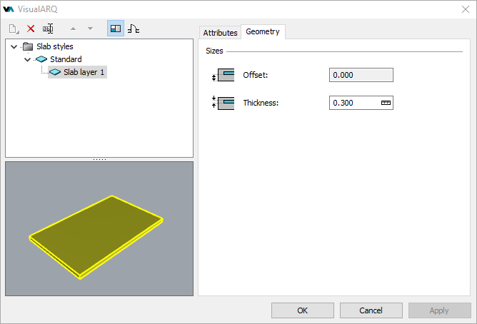
. - By style: open the slab styles dialog (vaSlabStyles command), select the layer component of the slab style (click on the triangle next to the style’s name to display the layer components), and change the thickness value from the Geometry tab.
Back to Index menu