Exercise 5. Create a Slab
1. Create a slab:
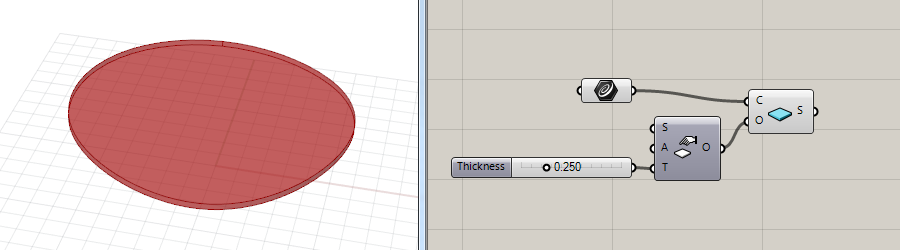
To create a VisualARQ slab in Grasshopper you just need a closed and planar curve.
- 1. Drag a VisualARQ Slab component
 onto the Grasshopper canvas. This slab component has two inputs:
- C: Boundary curve
- O: Options to specify all slab parameters.
- 2. Assign a curve into the slab C input. The curve will define the slab boundary and must be planar and closed. You can select multiple curves to generate multiple slabs.
The chosen curve(s) can be taken from Rhino (referenced in Grasshopper with the Curve Param) or be created directly in Grasshopper.
2. Define the slab parameters:
- 1. Drag a Slab Options component
 onto the Grasshopper canvas. This component has different inputs which define the slab parameters.
 - 2. Plug the Slab Options O output into the Slab component O input.
- 3. Set the different Slab Options:
- (S) Slab Style:
 You can drag a Slab Style Param component onto the canvas, plug it into the S input of the Slab Options. The current version of VisualARQ (1.8) has only one standard style available which is assigned by default. In future versions it will be possible to create and edit slab styles.
 - (A) Alignment:
 The Slab Alignment (Params tab > Architectural Inputs) defines the position of the slab relative to its boundary curve. There are three options available: top, center or bottom. These alignment positions can be also entered as integer numbers (0=Top, 1=Center and 2=Bottom) in the A input.
 - (T) Thickness: Slab thickness.
- (S) Slab Style:
3. Subtract a boundary from a slab
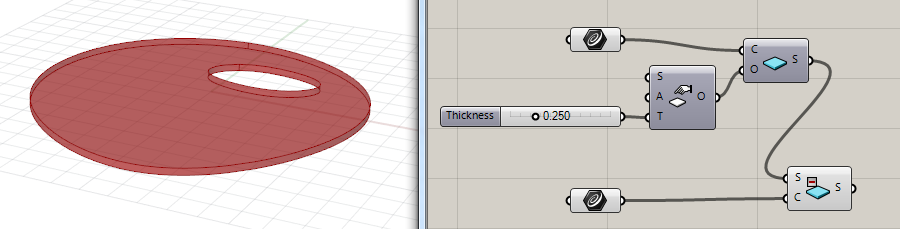
You can subtract a boundary curve from a slab or multiple slabs.
- Drag a Slab Subtract Boundary component
 onto the canvas.
 - In the S input plug, the slab you wish to subtract the boundary from.
- In the C input, plug the curve used as the boundary you wish to subtract. This curve must be flat and closed.
The boundary subtraction in slabs will be performed according to the area of the boundary curve projected vertically on the slab.
If the boundary curve is projected completely outside the limits of the slab, the subtraction won’t happen and won’t be visible.
Note: Boundaries do not need to be in the slab plane, but they must be planar and closed curves.
4. Link stair contours with slab holes
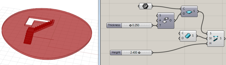
You can subtract the boundary of a VisualARQ stair from a slab object, maintaining a specified minimum clearance height between the stair path and the slab bottom surface.
- Drag a Slab Subtract Stair Clearance component
 onto the canvas.
 - This component has three inputs. Plug the corresponding components and values in:
- (S): Input Slab
- (St): Stair for the clearance
- (H): Clearance height: minimum clearance height between the stair path and the slab bottom surface
5. Create multilevel slabs from a volume
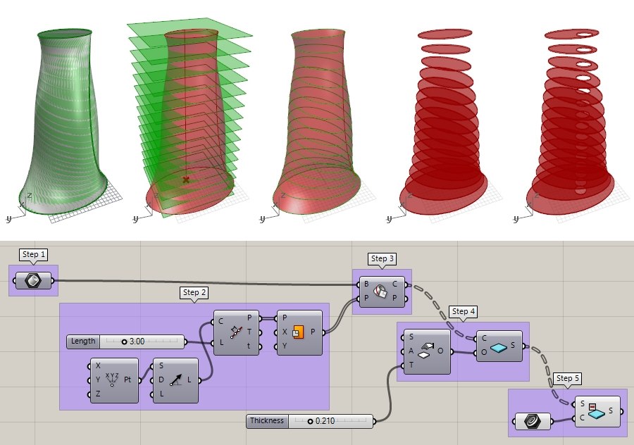
Step 1. Select a referenced Brep from the model: drop a Brep Param Component, right-click and select Set one Brep (volume) from the model (then hide the Brep in Rhino for a better workflow).
Step 2. Create intersection planes along the building height:
- Create a vertical line of the same height as the Brep. You can use a Line SDL for this purpose. This line needs the following information
- (S): Line start point (make sure the point is located at the volume base)
- (D): Line direction: (Unit Z vector)
- (L): Line length. Insert the building height, after measuring it.
- Divide the line in segments: each division will represent the different floors in the building.
- Drag a Divide Length component onto the canvas
- Plug the Line SDL component into the C Input (Curve to divide), and enter a number value into the L (Length of segments) Input.
- Create the planes: drag a Plane component and place it on the division points of the Divide Length component.
Step 3. Find the intersection between the horizontal planes and the Brep
- Drag a Brep / Plane component and plug the Base Brep into the B input and the Section Planes into the P input. The contour lines of the Brep will be created.
Step 4. Create the slabs.
- As explained in point 1 of this tutorial, drag a Slab Component onto the canvas, and plug into its C input, the intersection curves created in the previous step.
- Drag a Slab Options component to edit the slab parameters.
Step 5. Subtract a boundary curve from all slabs.
- Select Curve Param
 and set one curve in the model as the boundary curve to subtract from all slabs.
 - Drag a Slab Subtract Boundary component onto the canvas and plug it to the bondary curve and the slabs created.